This article explains what tributary areas are, why they are important and presents a simple geometric method to calculate them. The chosen units displayed in the examples is expressed in meters, but all numbers are applicable in feet as well.
How do columns work?
The fact that columns are everywhere in buildings may not be news to you. They play an incredibly important role in buildings as their main purpose is to transfer different kinds of loads from the structure down to the ground. When the loads arrive to the ground they are handled by the foundations and ultimately supported by the surface of the earth. The load the columns have to carry can come from many things:
- The weight of the structure itself (dead load), such as the floors and beams.
- Objects occupying the structure (live load), such as people, furniture and equipment.
- Wind, snow and earthquakes (environmental loads).
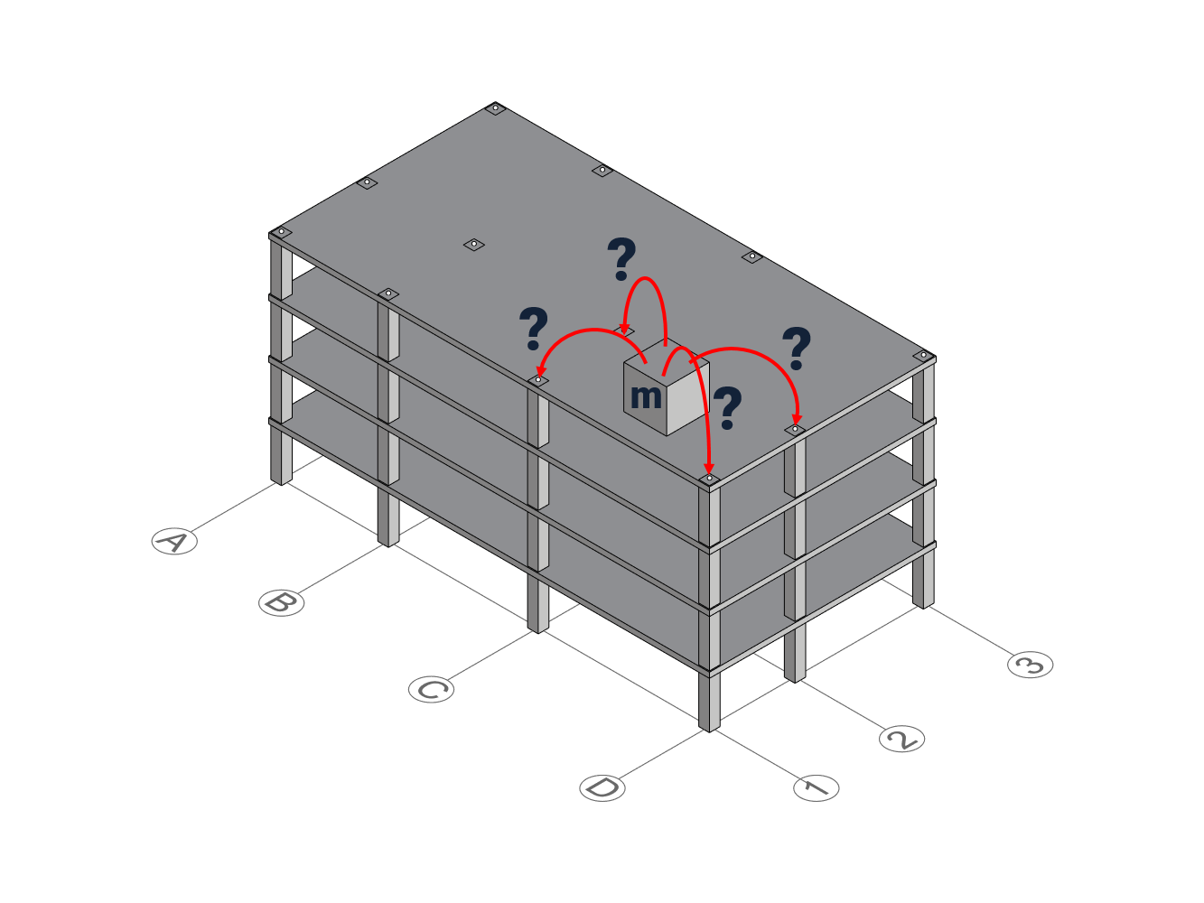
A very common duty of a column beloning to the first category (dead load) is to carry the weight from the slab resting on it. However, a slab is rarely supported by only one column – often times you see a bunch of columns organized in a structural grid beneath the slab.
So, if we wanted to understand how much load each column carries, then the inevitable question arises which part of the floors is carried by which columns? To solve this, the concept tributary areas comes in handy.
What are Tributary areas?
Tributary area, or sometimes referred to as influence area, is the area surrounding the column that absorbs the load. A quick google on the word “Tributary” leads us to this wikipedia definition that describes a geographical phenomena rather than a structural engineering concept:
“A Tributary [..] is a stream or river that flows into a larger stream or main stem (or parent) river or a lake.”
Interestingly, the same concept can be applied to columns and forces if we substitute rivers with columns, and water with forces. The gravitational forces from the slab flows into the column, and the tributary areas helps defining how much of the slab each column attracts.
How to calculate tributary areas
Calculating the exact tributary area can be tricky, because first we have to understand how the forces flow through the slab. Just like a wider river has more capacity to transport more water, a stiffer column has more capacity to “transport” (or transfer) more forces. Additionally, the slab can also have different stiffnesses in different direction, making the flow non-uniform. For instance, one-way slabs supported by infill beams are designed to transfer loads predominantly in one direction. Read more about the differences between one-way and two-way slabs here.
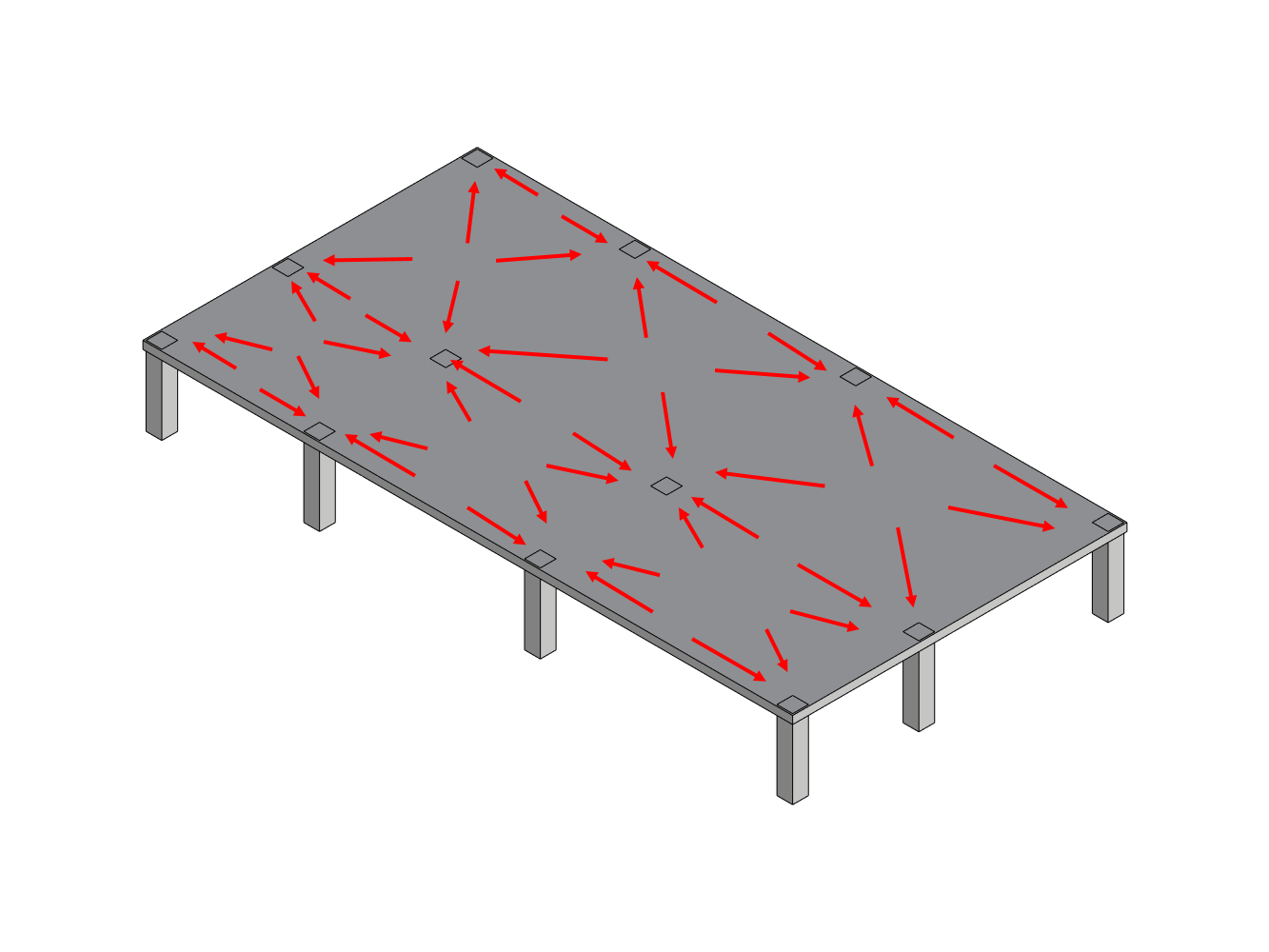
However, for the sake of simplicity, if we assume that the floor is isotropic and all columns below are equally stiff, then it ultimately boils down to geometric problem. From each given point of the slab, which column is the closest? To solve this problem, we can identify every column’s neighbor, and divide the distance in half by drawing a centerline. The area on the columns side of the centerline will be its’ tributary area.
This usually starts with finding the mid point between each pair of columns and draw a perpendicular line. When all perpendicular lines are drawn, the resulting bounding polygon defines the column’s tributary area.
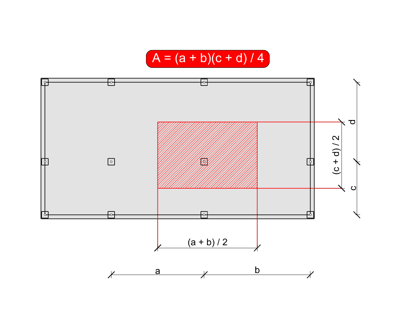
To summarize this, the tributary area is the area surrounding the column bounded by its’ centerline polygon. Following these simple steps we can approximate them easily:
- Identify the neighboring column in each direction
- Measure the distance between the pair
- Divide the distance by 2
- Draw a perpendicular line at this point.
- Repeat for all neighboring gridlines until a bounding polygon appears.
Example
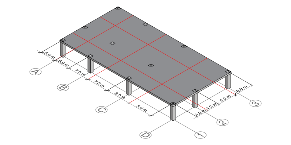
To exemplify how tributary areas can be calculate, let’s take a simple example structure. For a more involved structure, see this article. Please observe the structure below:
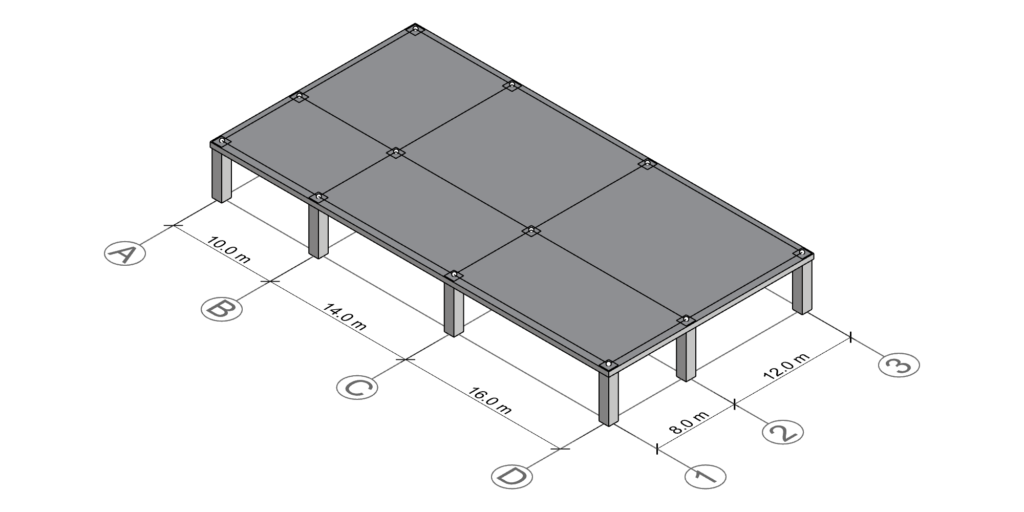
The slab has a rectangular shape and the columns are organized in parallel to the slab edges. The structural grid is made up of 4 grid lines in one direction, and 3 grid lines in the other direction. At every grid line intersection, there is a column.
Column D-1
Let’s start with column at the intersection D-1. As presented in the last section, we can follow these simple steps:
- Identify the neighboring column in each direction
D-1 is adjacent to gridline C and gridline 1. - Measure the distance
The distance between D-1 and C-1 is 16 meters, and the distance between D-1 and D-2 is 8 meters. - Divide the distance by 2
Half the distance D-1 and C-1 is 16/2=8 meters and half the distance between D-1 and D-2 is 8/2=4 meters. - Draw a perpendicular line at this point.
When the midpoints have been identified, proceed with drawing perpendicular lines.
Following the steps above, we end up with the following two lines marked in red:
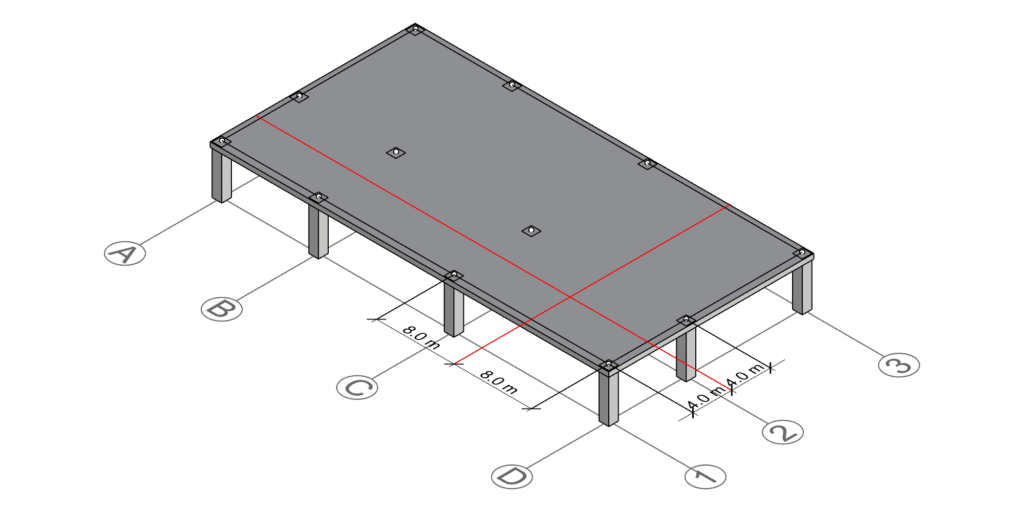
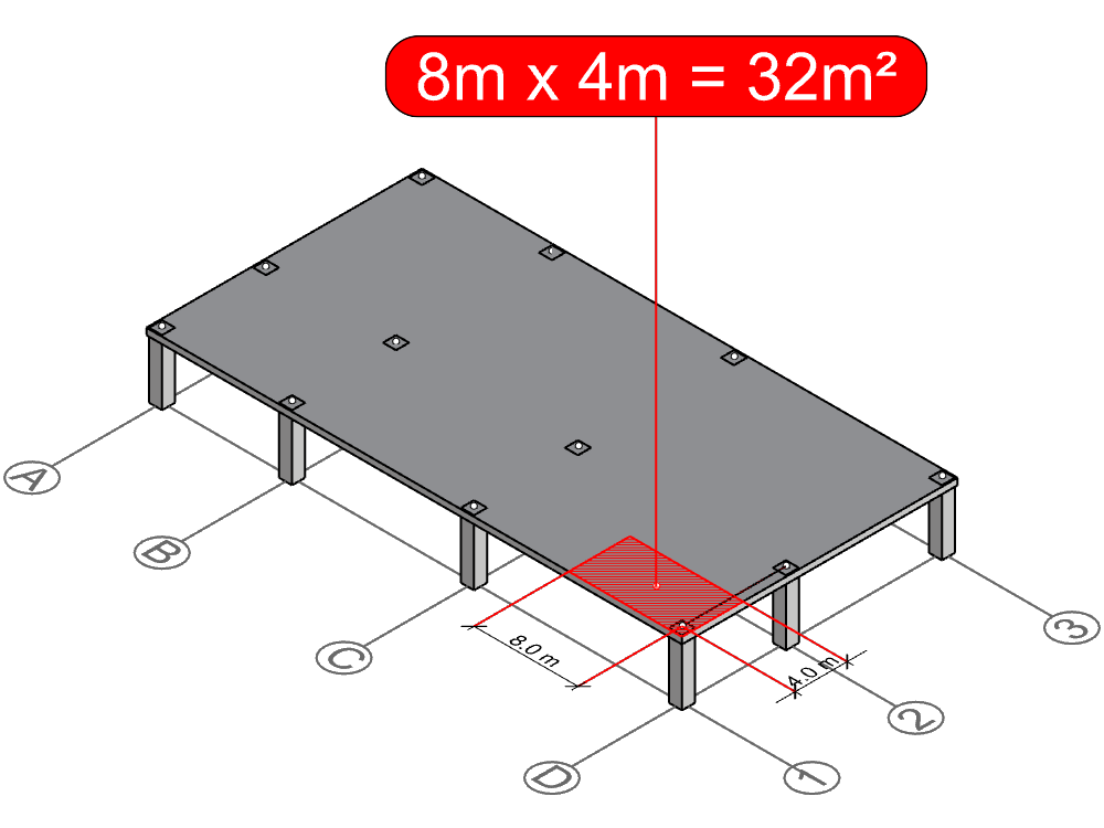
As you can see, the two drawn lines intersect in a common point. This point defines one corner of the tributary area polyline. Because column D-1 is located at a corner, it only has neighbors in along direction. Therefore, the other three corners of the rectangle are defined by the outer boundary of the slab.
Since the bounding polygon is a rectangle, we can easily calculate its area by multiplying the side lengths, and hence we have derived the tributary area of column D-1: 8m x 4m = 32m2.
Did you like this post? Sign up and we’ll send you more awesome posts like this every month.
Column C-2
Now, let’s do the same process for the interior column C-2. Start with identifying the neighboring gridlines. In this case the gridlines associated with C-2 has neighbors on both two sides;
- The left neighbor of gridline C is B
- The right neighbor of gridline C is D
- The left neighbor of gridline 2 is 1
- The right neighbor of gridline 2 is 3
Drawing the perpendicular centerlines between C-D, B-C, 1-2 and 2-3 gives us the following result:
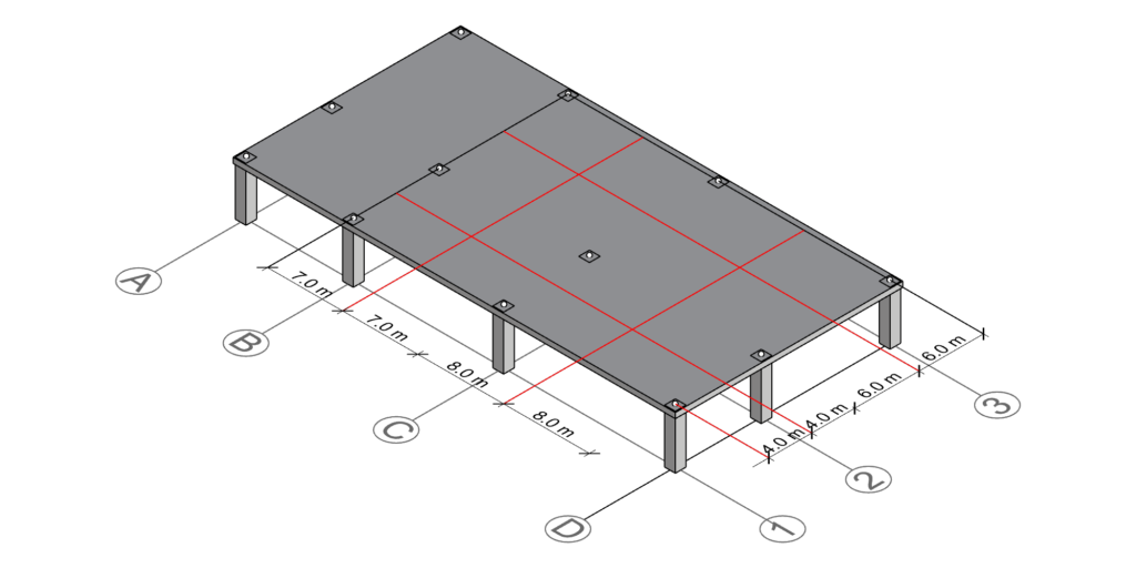
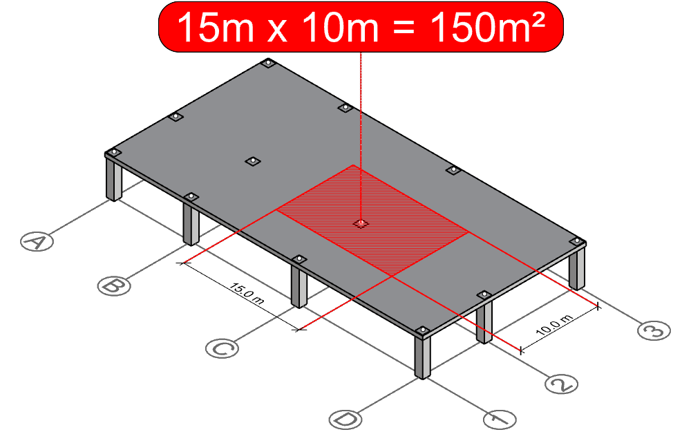
As you can see, column C-2 is surrounded by 4 intersecting lines, which defines the column’s tributary area boundary. By multiplying the side lengths of this rectangle, we can calculate the area of this rectangle and hence derive the tributary area of column C-2 15m x 10m = 150 m2
All columns
To complete this exercise, we can repeat the process for all columns. As you can see, many of the centerlines are shared between multiple tributary areas, which saves us some time:
Having the centerlines defined, we can draw the bounding polygon and hence derive the tributary area for each column:
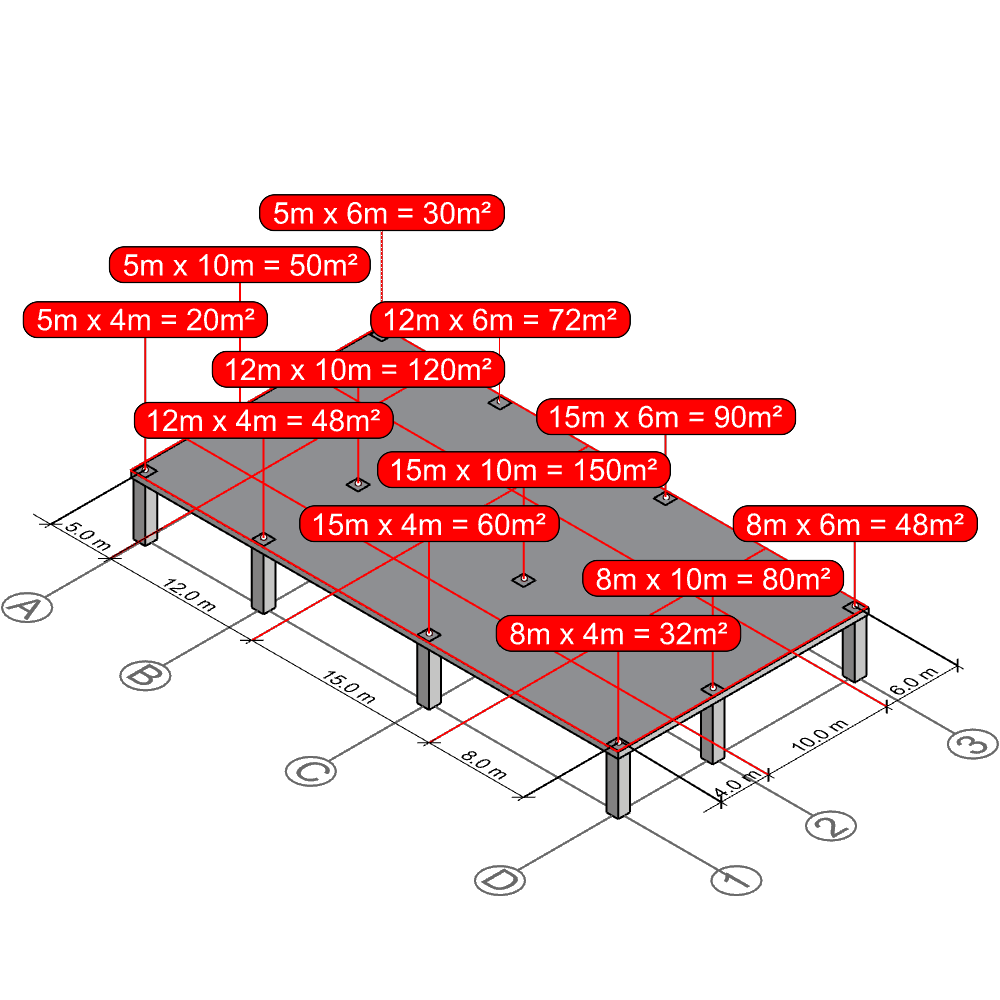
That’s it! Calculating tributary areas of columns isn’t harder than this.
Conclusion
In this article we have demonstrated a simple geometric approach for calculating column tributary areas. Note that this method is an approximation and assumes that the supporting columns are equally stiff. Furthermore the slab is assumed to carry loads uniformly in all directions. The example structure shown in the article is also regular, which makes the calculation easier. For an example with an irregular configuration, please see this article.
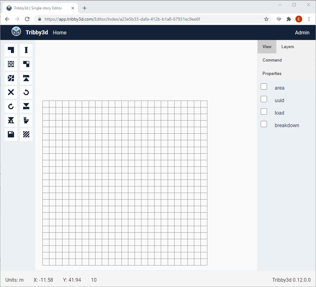
The method can be carried out using hand sketches or drawn in a CAD software. However, if the structure is large and involves many columns, then automating this process can save hours of manual work. A software that is able to automate this is Tribby3d. It allows users to sketch slabs, columns, walls and area loads in an interactive modeling environment. Subsequently the user can solve the configuration’s tributary areas in a matter of milliseconds. Check out the gif below for calculating the column tributary areas of the example presented in this article using Tribby3d:
If you’re interested in testing the free beta version of Tribby3d, please sign up here: https://tribby3d.com/sign-up
You can also test an open version of Tribby3d here, without the requirement to sign-up: Free Tributary Area Calculator.