In this article, we discuss the concepts around bending moment. We also provide equations and calculators for common beam configurations.
Why Is Bending Moment Important?
The design of structures incorporates the effects of loading. To keep the stability of structures, resistance to bending moment is therefore crucial. Examples of loads can for instance be live load (the people or objects in the building), dead load (the weight of the structure itself), and environmental loads (snow load, wind load and earthquakes). Damage can happen due to bending whenever the bending stress exceeds the element’s ultimate strength.
Capacity vs demand
Dead loads and live loads both act simultaneously on structures, changing how all its components interact. As a result, while designing a structure for optimal stability, engineers must consider both. A beam’s capacity to withstand load is a computation that aids in determining the building’s overall structural soundness. Because no material can withstand an infinite load, engineers calculate the “bending moment” when considering external forces.
External forces
Three forces effect the structural design parameters of loads:
- Compression occurs when particles of a substance are pressed against each other, shortening, or compressing them. Compression is typically applied from the top of a structure. Read more about compression and the effects it can have in this article: Column buckling
- Tension is the total opposite of compression; in tension the material is pulled by the pulling forces. The beam is under tension load when the beam fails at top.
- The twisting force that act on a structural part is known as Torsion.
The above three stresses are always present in structures. For instance, assume you are strolling over a house’s second level. Your weight will then compresses the beams that support the floor. Consequently the beams compress at the top, they stretch out in tension at the bottom. This creates a bending moment. In addition, the shear web keep the beams together. In conclusion, the home’s structure must be able to balance all of these pressures to preserve structural integrity.
What is Bending Moment?
The measure of the effect of bending due to the applied transverse force to a structural element is known as bending moment. In structural engineering, the bending moment is therefore an important element in the design of structures. Otherwise, it would be hard to understand the behavior of structural elements under the application of transverse load. As previously mentioned, the design of the structure is keeping the maximum bending limits of the structure within the permissible limits. However, by exceeding bending or shear limits, the structure will fail to keep its stability and will ultimately result into failure.
How is Bending Moment Calculated
When transverse force is applied on a section of beam, the stresses produced will be known as bending stresses. Consequently, applied forces cause the bending moment which is commonly quantified as force x distance (kN-m). While measuring the bending, the force must be perpendicular to the moment arm. The beam is the most common structural element subject to bending moments, as it can bend at any point along its length when loaded. Despite the differences in processes, a beam may collapse owing to shear stresses prior to bending failure. In that case, the bending force will force the beam to revolve around the pivot point if the pivot point is not properly confine. The point at which maximum bending moment occurs is therefore important for the flexural design of the structure.
Derivation of Bending Moment Equation
To understand the full context of bending moments, we must study the cross section of a beam in bending.
Discrete strip of bending stress
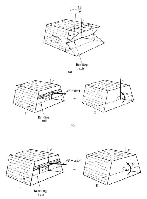
From the figure, we can see that internal stresses are statically equivalent to the external forces and moment. Firstly, consider a dF amount of force exerted on the strip area of dA. The stress σ developed will be given as

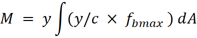
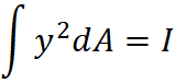
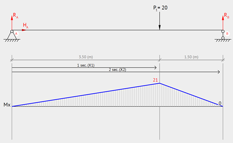
Consequently, the moment M will be given as

Here, y is the distance of force from the neutral axis (i.e. the point at which there is no tension or compression acting on the beam). Subsequently, to derive the maximum stress at extreme fiber, fb, we can use a trigonometric trick:
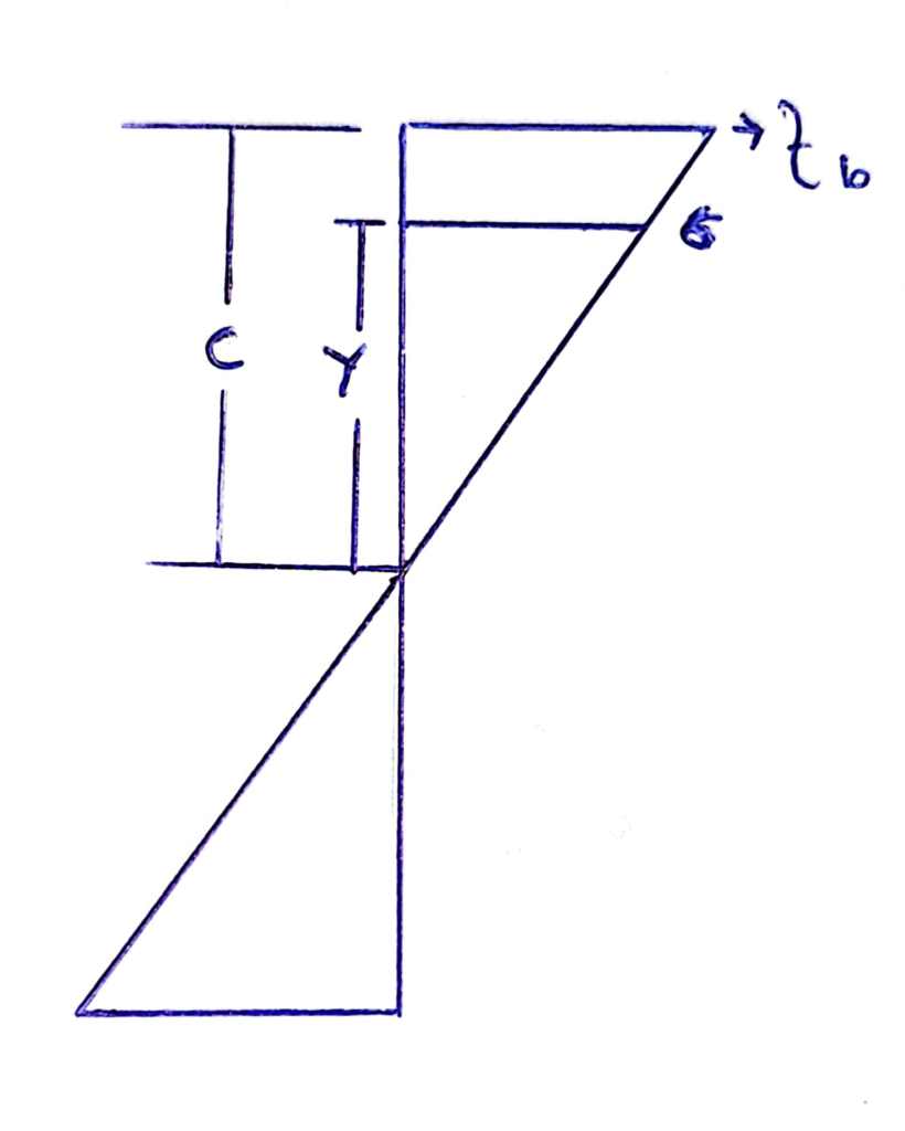
From similarity of triangles in the above figure we can get

Rearranging the above equation
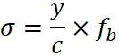
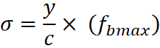
Where c is the distance from the neutral axis to the top of the cross-section, fbmax is the maximum stress at extreme fiber and σ is flexural stresses on the strip at distance.
Integration of bending stress
We can now plug this into the first equation. However, in the inititiation of equation derivation, a single strip of the cross section was assumed. To include the entire cross section, integration is taken;
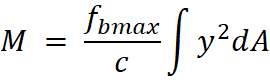
Here, we identify that the definition of second moment of area, I, can be used to simplify the equation.
![=f_b/c [I]](https://tribby3d.com/wp-content/uploads/sites/4/2022/02/image030.png)
Rearrange for fbmax (Bending stress)

So, stress fb at any distance, y from neutral axis will be

We can also write

Where S is section modulus I/Y.
Assumptions
Note that the derivation of bending moment equations above has the following assumptions:
- Firstly, the beam is linear and has a uniform cross-sectional area before stresses are applied.
- Secondly, the bending moment occurs inside the longitudinal plane of symmetry of the beam.
- Third, the beam is subjected to pure bending (bending moment does not change along the length).
- Finally, the material used in the beam is homogenous and isotropic.
Did you like this post? Sign up and we’ll send you more awesome posts like this every month.
Bending Moment Equations
The sections below contain the beam configuration along with applied load and formulas for calculating the maximum bending moment.
Cantilevers
In this subsection, we look at different loading configurations of cantilever beams.
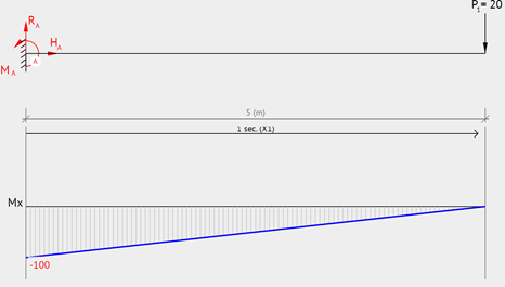
Cantilever – Point Load at End
A clamped beam with vertical point load at the end point will have its maximum moment at the support. To illustrate this, see moment diagram and equation below.
Equation & Diagram

Calculator
Following the equation above, use this calculator to compute the maximum moment of a cantilever beam with length L subjected to a point load P at the end.
| P: | |
| L: |
| M: |
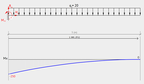
Cantilever – Uniformly Distributed Load
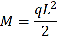
Similar to the configuration above, a clamped beam with uniformly distributed load will have its maximum moment at the support. To illustrate this, see moment diagram and equation below.
Equation & Diagram
Calculator
Following the equation above, use this calculator to compute the maximum moment of a cantilever beam with length L subjected to a point uniformly distributed load q.
| q: | |
| L: |
| M: |
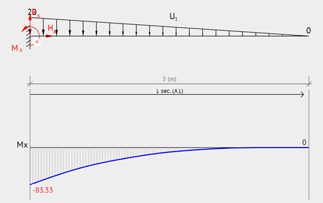
Cantilever – Triangular Distributed Load
Likewise the configuration above, a clamped beam with triangular distributed load will have its maximum moment at the support. To illustrate this, see moment diagram and equation below.
Equation & Diagram
Calculator
Following the equation above, use this calculator to compute the maximum moment of a cantilever beam with length L subjected to a point triangular distributed load q.
| q: | |
| L: |
| M: |
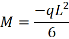
Cantilever – End Moment
A clamped beam with a moment load at the end will have constant moment throughout the entire beam. To illustrate this, see moment diagram and equation below.
Equation & Diagram

Calculator
Following the equation above, use this calculator to compute the maximum moment of a cantilever beam with length L subjected to a moment load M0 at the end.
| M0: |
| M: |
Simply Supported
In this subsection, we look at different loading configurations of simply supported beams. In other words, beams with one end pinned, and the other end on a roller.
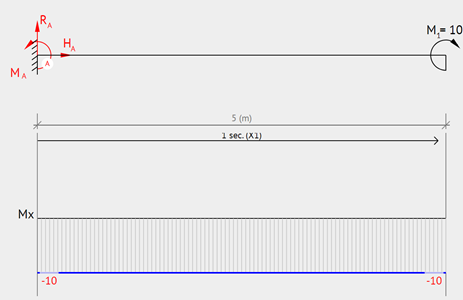
Simply Supported – Intermediate Load
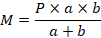
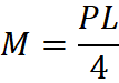
Now, if we look at simply supported beams, a common configuration is one with a point load at distance a from the first support.
Equation & Diagram
Calculator
Following the equation above, use this calculator to compute the maximum moment of a simply supported beam with total length a + b subjected to a point load P located at distance a from the support.
| P: | |
| a: | |
| b: |
| M: |
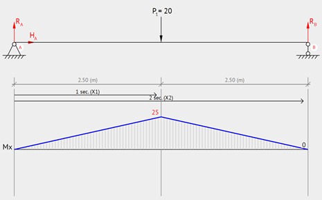
Simply Supported – Center Point Load
Simply supported beam with a point load at the center. The maximum moment occurs where the point load is applied.
Equation & Diagram
Calculator
Following the equation above, use this calculator to compute the maximum moment of a simply supported beam with length L subjected to a point load P at the center.
| P: | |
| L: |
| M: |
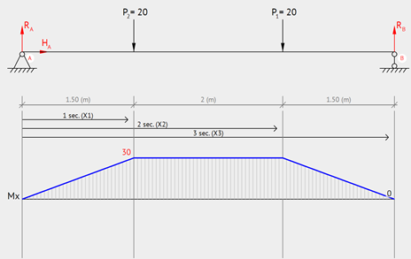
Simply Supported – Two Point Loads at Equal Distance from Supports
Simply supported beam with two point loads at equal distance from the supports. The maximum moment occurs between the two point loads.
Equation & Diagram

Calculator
Following the equation above, use this calculator to compute the maximum moment of a simply supported beam with length L subjected two point loads at equal distance a from the supports.
| P: | |
| a: |
| M: |
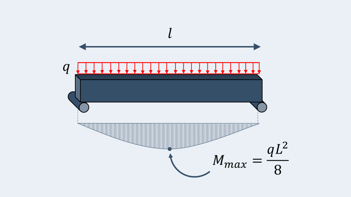
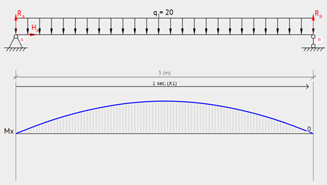
Simply Supported – Uniformly Distributed Load
Simply supported beam with a uniformly distributed load on it. The maximum moment occurs at the center of the beam.
Equation & Diagram
Calculator
Following the equation above, use this calculator to compute the maximum moment of a simply supported beam with length L subjected to a uniformly distributed load q.
| q: | |
| L: |
| M: |
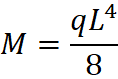
Simply Supported – Moment at Each Support
Simply supported beam with two point moment loads at each end. The moment is constant along the length of the beam.
Equation & Diagram

Calculator
Following the equation above, use this calculator to compute the maximum moment of a simply supported beam with length L subjected to two moment loads M0 at the ends.
| M0: |
| M: |
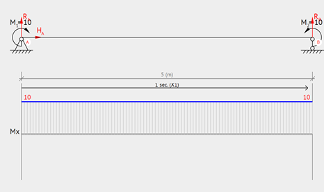
Simply Supported – Moment at one Support
Simply supported beam with moment load at one support. The moment diagram is triangular, where the maximum moment occurs where the moment is applied.
Equation & Diagram
Calculator
Following the equation above, use this calculator to compute the maximum moment of a simply supported beam with length L subjected to one moment load M0 at one end.
| M0: |
| M: |
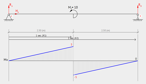
Simply Supported, Moment at the midpoint
Simply supported beam with moment load applied at the center. The maximum moment will occur at the center.
Equation & Diagram

Calculator
Following the equation above, use this calculator to compute the maximum moment of a simply supported beam with length L subjected to one moment loads M0 at the center.
| M0: |
| M: |
Conclusion on Bending Moment
In conclusion, a bending moment is the reaction that occurs in a structural element when it is subjected to an external force or moment that causes it to bend. The beam is the most typical or simplest structural member that is prone to bending moments.
To examplify this further, consider the moment (force) on an elbow . As mentioned previously in the article, the moment is directly proportional to the lever arm. Similarly, it plays significant role in determining the design parameters for cantilever structures. If the moment exceeded within the design strength the structure, or any other component due to excessive load then it may collapse. The failure in the World Trade Center towers were due to an increase now in connections produced by the extreme heat of the fires. When moments in a structure change, the transmission of forces to other elements, connections, and components of the overall system become uncontrollable, which can lead to failure.
Finally, engineers design structures using software nowadays to get accurate and fast results. For example Tribby3d, which is a cloud based structural loading software. Using tribby3d, engineers can easily calculate tributary areas and element loading of various element types such as columns and walls. The results can then be exported to various outputs, such as Excel and AutoCAD.